
Specialized heavy lift field study
Helicopter Drop Testing for Certification and R&D Programs
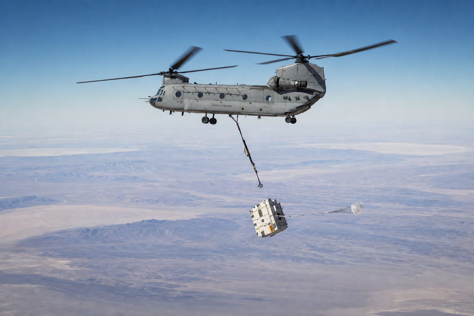
Helicopter drop testing releases instrumented test articles weighing up to 28,000 pounds from a stabilized hover or forward flight, at heights from a few feet above the surface to nearly 20,000 feet. Operators execute these missions under 14 CFR Part 133 Class B jettisonable load procedures, logging release conditions, GPS position data, and video for every drop.
The mission set
What Is Helicopter Drop Testing Used For?
A drop test program lives or dies on the quality of its release conditions. The test engineer needs the article delivered to a defined point in space, at a defined attitude, at a defined velocity, and released on command with the instrumentation running. A rotorcraft is the only release platform that can hold all four variables simultaneously across a wide envelope: zero forward airspeed in a stabilized hover, or a controlled forward-flight release; release heights from ground effect to the aircraft's service ceiling; and repositioning between drops measured in minutes, not test days.
Aerial drop test services built on that flexibility serve four recurring program types:
- Airframe certification drop testing. Fuselage sections, seats, and fuel system crashworthiness articles dropped to certification impact conditions where the required impact velocity maps to a specific release height.
- Parachute and airdrop system qualification. Deployment testing of cargo parachutes, recovery systems, and airdrop rigging at controlled release altitudes and airspeeds, repeated across the test matrix in a single flight day.
- Munitions-adjacent inert testing. Release of inert test shapes and stores on government ranges under range control authority, with the release geometry documented per the test plan.
- Container and packaging qualification. Drop qualification of shipping containers, transit cases, and engineered packaging against impact criteria that fixed drop rigs cannot reach at full article weight.
Each mission is engineered as a rotorcraft external load operation first and a test event second. The physics that govern a production lift (load parameters, rigging design factors, density altitude) govern the test release just as strictly. The full regulatory framework is documented on the External Load Operations pillar page; this page covers what changes when the load is a test article and the objective is a clean release.
The release system
How the Release Mechanism Works Under Part 133
Every Part 133 Class B external load is, by regulatory definition, a jettisonable load: the cargo hook carries an electrical release actuated by the pilot, backed by a manual mechanical release as an independent second means. In production lifting, that release system is an emergency provision. In drop testing, it is the primary test instrument.
That distinction matters to the test engineer for three reasons:
- The release system is certified, inspected, and exercised. The hook, electrical actuation, and mechanical backup are part of the aircraft's approved Rotorcraft-Load Combination Flight Manual (RLCFM) configuration, not a custom fixture bolted on for the test. Release reliability is an airworthiness item, validated before the aircraft launches.
- Release is a pilot action on a countdown, not a remote guess. The pilot in command actuates the release on the test conductor's mark, with the aircraft stabilized on condition. Timing between "on condition" and "load away" is coordinated in the pre-mission brief and rehearsed on the practice drop.
- Dual-path release protects the test article. If the primary electrical circuit fails with an instrumented, long-lead-time article on the hook, the mechanical release and the abort procedure bring the article back to the staging area intact. A hung load is an abort, not an improvisation.
Where a program requires a test-specific release fixture (a swivel-mounted quick-release, a static-line arrangement for parachute deployment, or a multi-point release frame), that hardware rides below the certified cargo hook and is engineered to the same ASME B30.20 below-the-hook standard that governs the rest of the operator's rigging inventory.
| Load path element | Function at release |
|---|---|
| Certified cargo hook | Carries the load; part of the approved RLCFM configuration |
| Electrical release | Pilot-actuated primary release, fired on the test conductor's mark |
| Manual mechanical release | Independent second means backing the electrical circuit |
| Swivel | Rotation control so the article separates without imparted spin |
| Long line | Rigged at a 7:1 design factor; sets suspension geometry |
| Sling set | Rigged at a 5:1 minimum design factor from engineered lift points |
| Instrumented test article | Certified weight and center of gravity from the test organization |
The Part 133 Class B jettisonable load path, read from the certified cargo hook down to the test article.
The envelope
What Is the Drop Test Release Envelope for Altitude and Airspeed?
The usable drop test release envelope is defined by three boundaries: the aircraft's performance ceiling, the RLCFM airspeed limitation for the specific rotorcraft-load combination, and the range safety template.
Altitude. Release heights run from a few feet above the impact surface (crashworthiness and container drops requiring low, precisely measured heights) up to high-altitude profiles. The CH-47D and the S-70M Black Hawk both offer service ceilings near 20,000 feet for altitude-release work such as parachute system qualification. Practical release altitude on any given day is a density altitude calculation, not a brochure number: engine power available falls roughly 3 percent per 1,000 feet of density altitude, and a 10 degree Fahrenheit rise above standard temperature adds roughly 600 feet of density altitude. High-altitude release profiles are engineered against the article weight and the forecast conditions, then validated against actual conditions on test morning.
Airspeed. A stabilized hover delivers a true zero-airspeed release, the condition most fixed-wing platforms cannot provide at all. Forward-flight releases are flown up to the external load airspeed limit established in the RLCFM for that aircraft and load configuration. Aerodynamically unstable articles are flight-tested at incremental speeds before the full-condition release, the same buildup discipline used on any unstable external load.
Attitude and geometry. Long-line length, article suspension geometry, and any required article orientation at release are engineered into the rigging plan so the article arrives at the release point in the attitude the test plan specifies.
Release point precision
What Positioning Accuracy Is Achievable at the Release Point?
Release point accuracy is a function of the aircraft's hover stability, the reference system, and the wind. Programs define the tolerance; the operation is engineered to meet it. Three practices drive the achievable precision:
- Surveyed release points and GPS reference. The release point is surveyed and loaded as a GPS reference. The aircraft is flown to the point using GPS position cueing cross-checked by ground reference, and the actual release position is recorded for the data package, so every drop carries its measured miss distance rather than an assumption.
- Vertical reference flying. Precision external load pilots fly vertical reference: looking directly down the line at the load. For low-altitude precision releases, this is the same skill set that places tower steel and rooftop units within inches on production work.
- Wind discipline. The pre-mission brief establishes wind limits for each test condition. A release that cannot be flown inside tolerance is held or scrubbed. On a test range, a scrubbed drop costs a window; an out-of-tolerance drop can cost the article and the data.
Programs requiring documented tolerances receive them in the test support plan, stated per condition, because a 10-foot hover release and an 18,000-foot parachute release are different problems and honest numbers differ between them.
The rigging plan
Rigging Instrumented Test Articles
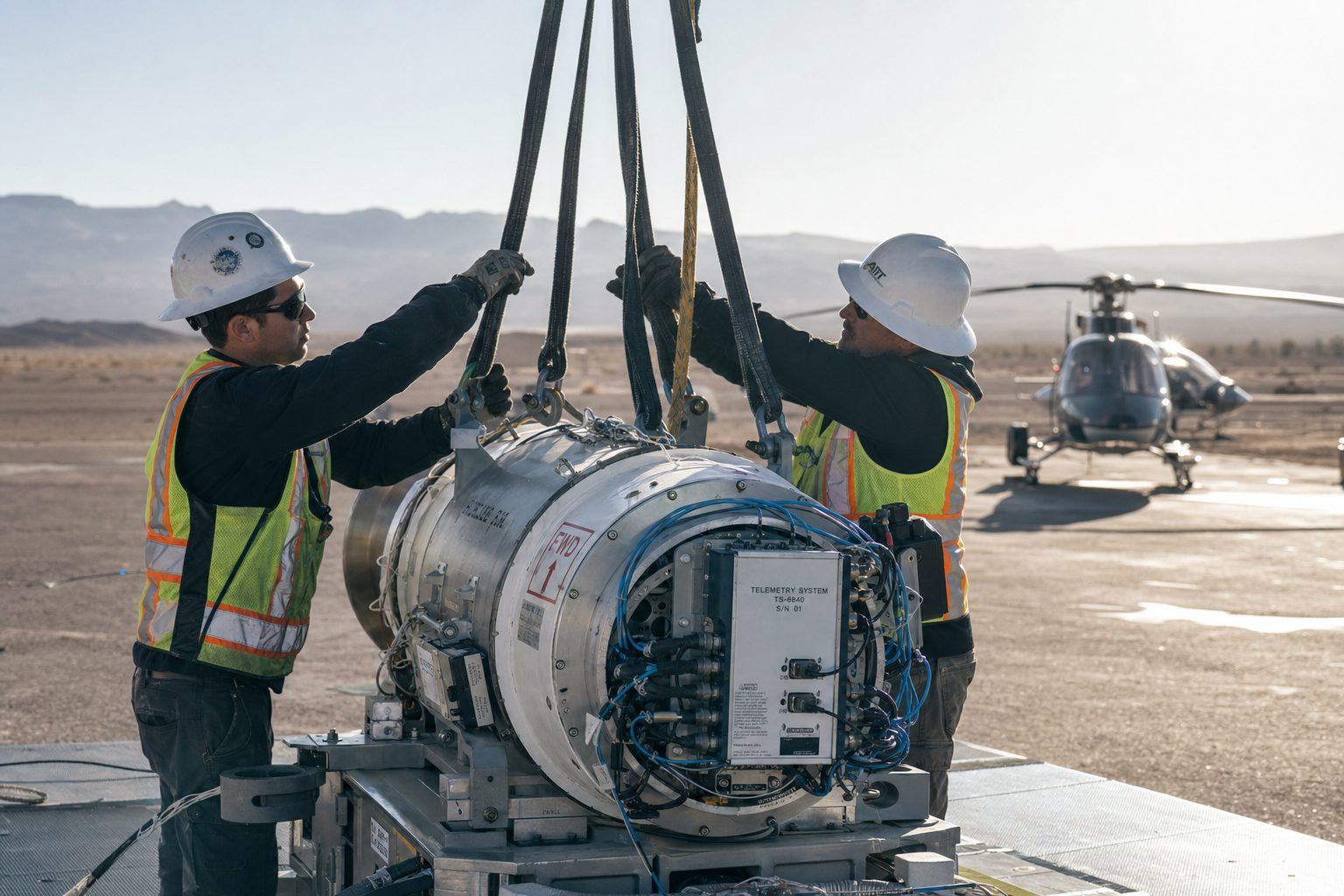
A test article is not general freight. It carries accelerometers, strain gauges, telemetry packages, cameras, and umbilicals, and it frequently represents months of fabrication lead time. The rigging plan treats it accordingly.
- Design factors are non-negotiable. Slings rigged at a 5:1 minimum design factor and long lines at 7:1, per the standards detailed under ASME B30.26 rigging hardware and ASME B30.20 below-the-hook lifting devices.
- Rigging is engineered around the instrumentation. Attachment points are taken from the article's engineered lift points as documented by the test organization. Sling paths are routed clear of sensor fields, umbilical disconnects are engineered for the release event, and any lanyard-initiated instrumentation (pull-away triggers, static lines) is integrated into the release sequence and rehearsed.
- Anti-rotation control. Swivels and, where the article shape demands it, drogue or vane stabilization keep the article from imparting rotation that would corrupt attitude-sensitive data at release.
- The pilot in command holds final rigging authority. Under Part 133 doctrine, the PIC can refuse any load whose rigging integrity is not demonstrated. The test organization provides certified article weight and center-of-gravity data; the operator validates the rotorcraft-load combination against it. That division of authority is written into the test support plan, so range day holds no surprises.
Ground crew operations at the staging area and drop zone run under OSHA 1926.551 helicopter crane provisions: static discharge grounding before any crew member touches a suspended article, tag line control, and rigging inspection before every pick.
Range operations
Can Drop Tests Be Conducted on Military or FAA-Designated Ranges?
Yes, and most programs of consequence are. Government and military range work layers additional requirements over Part 133, and the operator must arrive already conversant in them:
- USACE EM 385-1-1. The Corps of Engineers safety and health manual governs contractor aviation operations on Corps and many DoD-adjacent programs. Aviation ground and flight operations, crew qualifications, and lift planning documentation are structured to EM 385-1-1 expectations from the first submittal.
- Range safety authority. On a military or FAA-designated test range, the Range Safety Officer owns the range. Release headings, footprint templates, abort gates, hold points, and communication protocols are flown exactly as briefed under range control. The flight profile is engineered inside the range safety template, never negotiated against it.
- Airspace coordination. Restricted areas, MOAs, and temporary flight restrictions are coordinated in the planning phase, including scheduling windows, frequencies, and squawk assignments, so that the flight test window is spent testing rather than resolving airspace.
For programs staged on private or remote land rather than an established range, the operator engineers the drop zone survey, surface danger area, and access control into the test support plan, and coordinates any required FAA airspace measures.
Aircraft selection
Which Aircraft Lift Which Test Loads?
Aircraft selection is driven by article weight, required release altitude, and cycle count. Civilian heavy lift aircraft in drop test service carry helicopter test loads from 8,000 to 28,000 pounds; all figures below are maximum external load capacities at standard-day, sea-level conditions. Density altitude on test day reduces them, and the mission plan states the corrected numbers.
| Aircraft | Max external load | Drop test role |
|---|---|---|
| Boeing CH-47D Chinook | 26,000 to 28,000 lbs | Heaviest articles; service ceiling near 20,000 ft for altitude-release profiles; tandem-rotor stability on the release point |
| Erickson S-64F Air Crane | 25,000 lbs | Heavy articles requiring precision release positioning; aft-facing pilot station gives the pilot direct view of the load |
| Sikorsky S-70M Black Hawk | 9,000 lbs | Mid-weight articles; ceiling near 20,000 ft; high cycle rate for multi-drop test matrices |
| Bell 214B Big Lifter | 8,000 lbs (long line) | Mid-weight articles and high-density-altitude test sites, with capability to 14,000 ft density altitude |
Repetitive light-article test matrices (container qualification series, parachute buildup drops) are matched to the smallest aircraft that carries the article with margin, because cycle economics, not maximum capacity, decide the cost per data point. The same matching logic applied to production work is described on the Specialized Heavy Lift hub.
The data package
What Documentation Package Accompanies Each Test Drop?
Data discipline is the difference between a lift company that drops things and a test support operator. Each release is delivered with a documentation package aligned to the program's test plan, typically including:
- Release conditions: pressure altitude and density altitude, indicated airspeed, heading, and winds at release, logged per drop.
- Position data: GPS-recorded release point coordinates against the surveyed target point, per drop, with miss distance.
- Time correlation: release event timing coordinated with range timing or the test conductor's instrumentation clock, so airborne events align with article telemetry.
- Video: airborne and ground-based video of the release and, where the test plan requires, the full descent and impact sequence.
- Configuration records: rigging configuration, release system checks, article weight and CG as certified by the test organization, and the flight crew and aircraft identification for the test record.
Chain-of-custody handling for instrumented articles and controlled test items is established in the support plan when the program requires it.
The honest boundaries
When a Helicopter Is the Wrong Release Platform
Solution-agnostic vetting applies to test support the same way it applies to construction lifting. Three cases where the answer is not a rotorcraft:
- Fixed-height, high-repeatability laboratory drops. A drop tower or gantry crane wins when the test calls for many identical low-height releases under laboratory instrumentation. The tower's repeatability at a fixed geometry beats any aircraft, and the hourly economics are not close.
- Release conditions beyond the rotorcraft envelope. High forward-speed release conditions belong to fixed-wing platforms. If the test matrix requires airspeeds above external-load rotorcraft limits, the honest recommendation is a fixed-wing test organization.
- Articles beyond 28,000 pounds. The civilian rotorcraft ceiling is 28,000 pounds on the hook. Heavier articles require ground-based release methods, and the program should hear that in the first conversation, not after a mobilization.
Everything between those boundaries, zero-airspeed to forward-flight releases, surface level to nearly 20,000 feet, single drops to full test matrices, is rotorcraft territory, and it is territory where a Part 133 operator with jettisonable-load discipline holds the advantage.
Planning the program
How a Drop Test Support Plan Comes Together
Test programs run on schedules set by certification milestones and range windows, and early coordination between the test organization and the operator protects both. The inputs an operator needs to engineer a test support plan are the article's certified weight and CG, the required release conditions per test point, the candidate range or site, and the instrumentation interfaces. From those, the test organization receives an aircraft recommendation, a rigging and release plan, range coordination scope, and the data deliverables list, structured to drop directly into its test readiness review.
For the regulatory framework behind every release, continue with the External Load Operations pillar. Within this vertical, Remote Site Freight covers logistics to remote range sites, and Disaster Relief examines the same rapid-mobilization discipline under emergency conditions. New operational analyses are announced through the mailing list; the signup opens from the Join the Mailing List button in the header.

Frequently asked questions
What Test Engineers Ask First
From the technical library