Rigging a helicopter lift is not ground rigging done in the air. The load lives in a dynamic flight environment where rotor-induced oscillation, gust response, and the transient forces of pickup and release load the hardware in ways a static crane pick never does. That is why the discipline is built on wider margins: slings at a minimum five-to-one design factor, non-human external longlines at seven-to-one, human external cargo at ten-to-one. Around those numbers sit the fundamentals that keep a load flying level and stable: a correctly located center of gravity, sling angles kept steep enough to control tension multiplication, below-the-hook and rigging hardware selected under ASME B30.20 and B30.26, anti-rotation control, and static discharge grounding before any hand touches the load. The pilot in command holds final authority over all of it and can refuse any load.
A rigging plan that would pass on a construction site can fail under a helicopter. The load is the same steel, the shackles are the same shackles, but the environment the load hangs in is completely different, and that difference is where rotorcraft rigging earns its separate body of practice. This article walks the engineering: why the flight environment changes the calculation, how the center of gravity and sling angles govern whether a load flies or fights, what the design factors are and why they are higher than crane practice, and which standards govern the hardware between the hook and the load. The regulatory frame around all of it is set out in the FAA external load operations rulebook.
Why rotorcraft rigging departs from ground-crane rigging
A ground crane holds its load in a nearly static state. The boom is rigid, the load is damped by the mass of the machine, and once the pick is stable the tension in the rigging settles to a predictable figure that changes slowly. A helicopter holds its load in none of those conditions. The aircraft itself is a moving platform reacting to control inputs and to the air it flies through, and the load hangs below it on a flexible connection that can swing, rotate, and oscillate.
Three phenomena drive the difference, and each one adds load that static rigging math does not see.
- Rotor-induced oscillation. The load hanging beneath the aircraft behaves like a pendulum, and the rotor downwash and control inputs can excite it. A load that starts to swing or to develop a vertical bounce feeds cyclic tension into the rigging that peaks well above the static hanging weight.
- Gust response. A gust that moves the aircraft moves the load a moment later, and the connection between them takes the difference. In forward flight, aerodynamic load on a bluff or sail-area cargo can push, lift, or yaw it, changing the direction and magnitude of the force the rigging carries.
- Transient forces of pickup and release. The instant the aircraft takes the weight, and the instant it sets the load down, are the sharpest loading events in the sequence. Taking up slack too quickly turns a static weight into a shock load, and a dynamic pickup can momentarily impose forces substantially higher than the load's actual weight.
None of these are exotic failure modes. They are the normal texture of external load flight, and they are the reason the rigging is not sized to the load's weight but to the load's weight multiplied by a margin that absorbs the dynamics. A rigger who treats an aerial pick as a crane pick has sized for the average and ignored the peaks.
Locating the center of gravity so the load flies level
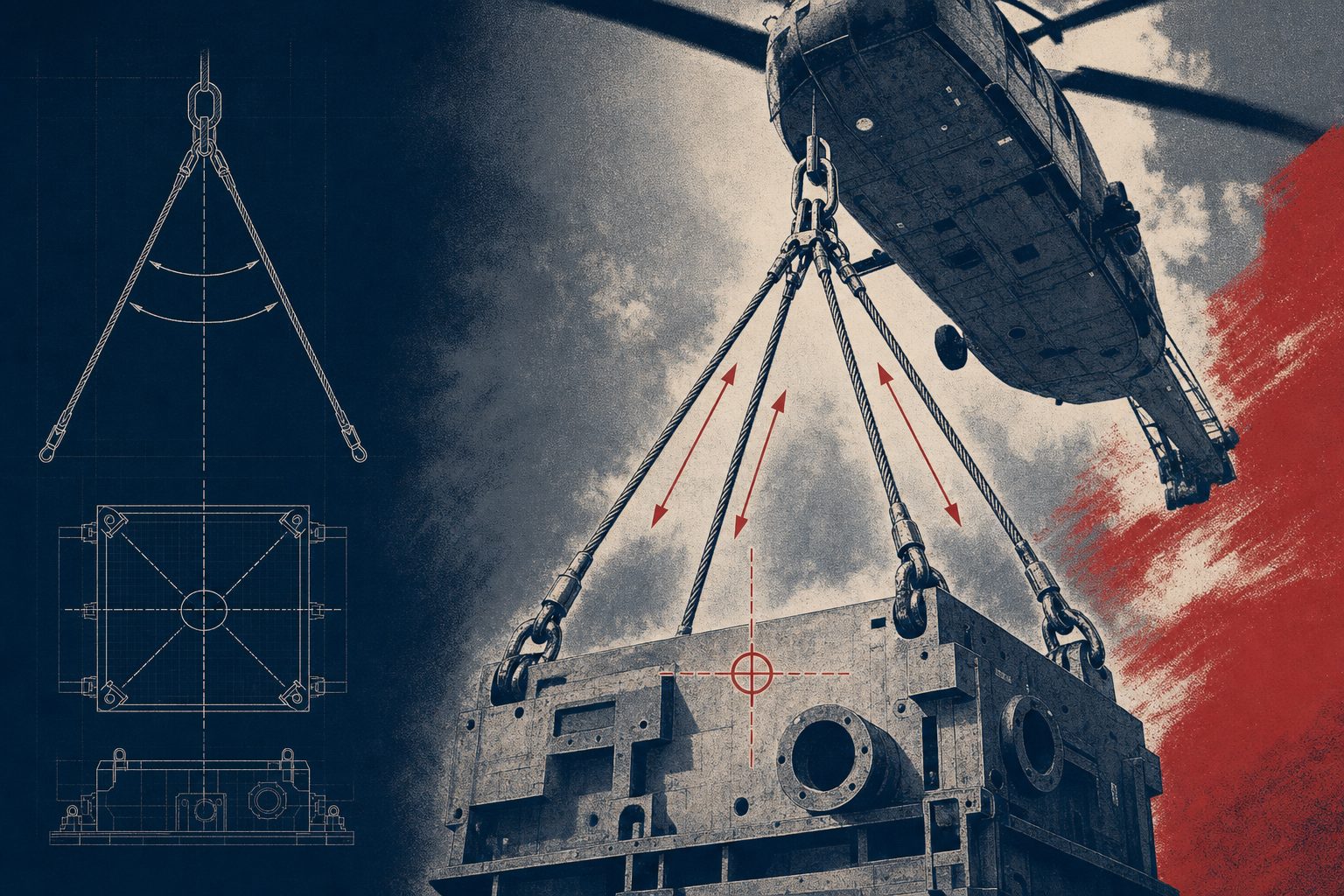
The single most important geometric fact about a load is where its center of gravity sits, because the aircraft's hook wants to hang directly above it. If the rigging is arranged so the resultant of the sling legs passes through the center of gravity, the load hangs level and stable. If it does not, the load tilts until the geometry balances, and a load that hangs nose-down or canted is both harder to place and more prone to catching air and swinging in flight.
For a symmetrical load the center of gravity is near the geometric center, and a symmetrical bridle flies it level. Real loads are rarely symmetrical. An HVAC unit with the compressor mass on one side, a transformer with its core offset, a length of pipe with a valve assembly on one end: each carries its center of gravity away from the middle, and the rigging has to be arranged to match. That means adjusting leg lengths, moving pick points, or using an asymmetric bridle so the lifting resultant still lands over the true center of gravity rather than the apparent center.
The contractor owns this input. Certified load weights and engineered pick points, including where the center of gravity actually is, come from the party that built or owns the load, not from a guess on the ground. When the center of gravity is unknown, the honest move is to establish it before flight, because discovering it on the hook, as a load that will not sit level, is the expensive way to learn.
Sling angles and tension multiplication
The most common way a rigging arrangement is quietly overloaded is through sling angle. When a load is lifted by a bridle of two or more legs, the legs spread outward from the hook to their pick points, and each leg makes an angle with the vertical. As that angle from vertical increases, the tension in each leg climbs, and it climbs far faster than intuition suggests, because the leg has to supply both the vertical force that holds the weight and a horizontal force that pulls against the opposite leg.
The vertical share of the load that each leg carries is fixed by the geometry, but the actual tension in the leg is that vertical share divided by the cosine of the angle from vertical. At small angles the penalty is negligible. Past forty-five degrees it becomes severe, and a shallow bridle that looked adequate can be carrying nearly double, or more, the tension a rigger estimated from the load weight alone.
The table below is illustrative. It shows the tension in a single leg of a two-leg bridle lifting a 10,000 pound load, where each leg carries a 5,000 pound vertical share, as the angle from vertical increases. The figures are geometric and do not yet include the dynamic flight margin discussed above. They exist to show the shape of the curve, not to size any specific pick.
| Angle from vertical | Tension multiplier (1/cos) | Tension per leg (illustrative, 5,000 lb share) |
|---|---|---|
| 0 degrees (straight up) | 1.00 | 5,000 lb |
| 15 degrees | 1.04 | 5,180 lb |
| 30 degrees | 1.15 | 5,770 lb |
| 45 degrees | 1.41 | 7,070 lb |
| 60 degrees | 2.00 | 10,000 lb |
| 75 degrees | 3.86 | 19,320 lb |
The lesson is that steep is safe and shallow is expensive. At sixty degrees from vertical each leg is carrying double its share, and at seventy-five degrees it is carrying nearly four times. This is why a bridle is kept as steep as the load geometry allows, why longer legs are preferred over short ones for a given spread, and why a spreader bar is introduced when the pick points are far apart. The spreader turns what would be a shallow, high-tension bridle into vertical or near-vertical legs by carrying the horizontal force in compression across the bar instead of in tension through the slings.
Design factors and why the flight environment demands them
A design factor, sometimes called a safety factor, is the ratio between the rated breaking strength of a component and the working load it is allowed to carry. A five-to-one design factor means the component is rated to break at five times its allowed working load. The margin is not waste. It is the room that absorbs the dynamic forces, the wear and handling damage a component accumulates, the manufacturing tolerances, and the uncertainty in the load itself.
Rotorcraft external load work uses higher design factors than much of ground rigging precisely because the flight environment adds the dynamic loading that ground picks avoid. The margins step up with the consequence of failure, and human external cargo carries the highest margin of all.
| Application | Minimum design factor | Why the margin is set here |
|---|---|---|
| Slings and rigging in external load work | 5:1 | Absorbs dynamic flight loading, oscillation, and handling wear on the connection between hook and load |
| Non-human external cargo longlines | 7:1 | A single load-path line carries the whole pick through gust and pickup transients with no redundant leg to share a peak |
| Human external cargo (personnel) | 10:1 | A person on the line makes any failure fatal, so the margin is set well above cargo practice |
The progression tells the story. A multi-leg sling arrangement has some redundancy and shares its load across legs, so it sits at five-to-one. A longline is a single load path from the aircraft to the cargo, so it climbs to seven-to-one because there is no second leg to catch a transient peak. Human external cargo, whether a rescue technician or a lineman being placed on a structure, sits at ten-to-one because the failure of that line is not a dropped load, it is a lost life. These are minimums, not targets, and the correct working figure for any pick is the one that keeps every component below its rated load after the dynamic margin is applied.
Below-the-hook devices and rigging hardware under ASME B30
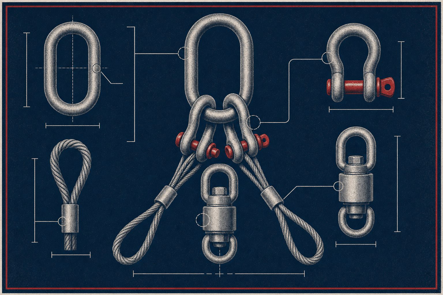
Everything between the aircraft hook and the load is governed hardware, and it divides into two families under the ASME B30 standards. Understanding which standard covers which component is how an estimator confirms that a rigging bill of materials is complete and correctly rated.
- Below-the-hook lifting devices, ASME B30.20. These are the engineered structures that shape how the load is picked: spreader bars, lifting beams, and similar fixtures. They are the tools that turn a shallow, high-tension bridle into vertical legs, or that provide multiple balanced pick points on a load that has only a few. Each is a rated device with its own capacity, and it is selected against the load and the geometry, not improvised.
- Rigging hardware, ASME B30.26. This is the detachable hardware that connects the assembly: shackles, master links, rings, turnbuckles, and swivels. Each piece carries a rated working load, and the rule is simple, every link in the chain of hardware must be rated at or above the tension it will see, including the multiplied tension from sling angle and the dynamic margin.
The wire-rope longline sits alongside these as the connection that lengthens the standoff between the aircraft and the load, keeping the rotor and its downwash clear of tall or fragile cargo and giving the pilot a longer, more stable pendulum to fly. The longline is a rated component like any other, inspected and retired against the same criteria, and it is the element that carries the seven-to-one factor when it is the single load path. The discipline across all of it is that no component is ever the unknown in the assembly. Every shackle, link, sling, and bar has a rating, and the whole chain is only as strong as its lowest-rated part.
ASME B30 Rigging hardware standard
Anti-rotation control and static discharge grounding
Two hazards specific to aerial work are managed with dedicated hardware and procedure rather than with the sling calculation. The first is rotation. A load hanging on a single point, especially a long or bluff load in a longline pick, can begin to spin under aerodynamic and torsional effects, and a spinning load is both hard to place and capable of winding up a line. Rotation is controlled with anti-rotation measures: a swivel that lets the line turn without transmitting spin into the load, a drogue or fin that uses the airflow to stabilize heading in forward flight, and tag lines handled by the ground crew to orient the load as it comes in to the set point.
The second is static electricity. A helicopter flying through the air builds a substantial static charge, and that charge sits on the load and the hook until it finds a path to ground. If the path is a ground crew member reaching up to receive the load, the discharge goes through that person. The procedure that prevents it is grounding: the load or the longline hook is bonded to earth with a static discharge conductor, or the charge is bled off with a grounding probe, before any crew member makes contact. This is not optional and it is not a judgment call. Under OSHA 1926.551, which governs helicopter crane operations, the charge is dissipated before anyone touches the suspended load, along with the standard's requirements for tag lines, personal protective equipment, and rigging inspection. The rule that any crew member can call an abort, and that a single designated signal person directs the aircraft, belongs to the same ground-crew discipline.
OSHA 1926.551 Ground crew rule
Authority and responsibility: who owns what
Rigging integrity has a clear chain of responsibility, and it matters because it tells a contractor where their own obligations sit. The contractor, as the party that owns or built the load, supplies the certified load weights, the center of gravity, and the engineered pick points. Those are the inputs the entire rigging design rests on, and a plan built on estimated weights is a plan built on sand.
From there the operator engineers the rigging: the sling type and rating, the angles, the below-the-hook devices, the hardware, and the design factor applied to each. And above all of it sits the pilot in command, who holds final legal authority over the rigging integrity of any load the aircraft picks. The pilot can inspect the rigging, question the weights, and refuse any load that does not meet the standard, and that authority is not a courtesy the contractor extends. It is the last gate in the system, and an operator whose pilots exercise it is demonstrating exactly what prequalifying a helicopter lift company is supposed to surface: margins that are real.
Reading a rigging plan as a buyer
An estimator or project engineer does not need to size the rigging themselves to judge whether it has been sized well. The signals are legible. A sound rigging plan states the certified load weight and the center of gravity rather than an estimate. It shows sling angles kept steep, and it introduces a spreader bar when the pick points force the legs shallow. It names the design factor for every component and applies the higher longline and personnel factors where they belong. It lists the below-the-hook devices and the hardware by rating, under the B30.20 and B30.26 standards, with no unrated part in the chain. It specifies anti-rotation control and the static grounding step. And it reflects, in writing, that the pilot in command holds refusal authority over the whole assembly.
A plan that carries those elements is one where the dynamics of flight have been engineered out in advance. A plan that carries the load weight and little else is a crane plan wearing a helicopter's name, and the gap between the two is exactly the margin that the flight environment will find. The rigging is the quiet part of an aerial lift, the part that never makes the schedule conversation, and it is also the part that decides whether the pick is a routine morning or an emergency load release over an occupied site.